
Q: Can you provide some background information on the role of the screw fastener in fire-resistive construction?
A: The fasteners that are used to mechanically attach the gypsum panel to the framing are vital to the success of the fire-resistive wall. The use of the wrong fastener or one that is improperly spaced can have a negative effect on the overall system’s fire-resistance performance. Another cause for concern is when the fastener has crushed the gypsum core beneath the head of the screw, thus negating the fastener’s holding power.
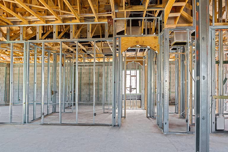
The performance of a fire-resistive assembly is predicated on its individual components. The gypsum panels must retard heat transfer through the assembly and act as a barrier against water breaching the assembly during the hose stream portion of the test. The framing, either wood or steel, must keep the gypsum panels in a vertical plane throughout the fire and hose stream portions of the fire-resistance test. The fastener is then critical in keeping the gypsum panel attached to the framing.
The hose stream is a very important part of the test program. The intent of the hose stream is to simulate falling debris during a fire that may literally impact the wall. To provide the needed fire separation, the wall must be able to withstand this impact. For a one-hour fire-resistance rating, a wall must be subjected to a stream of water at 30 psi pressure for one minute. The wall must remain in place throughout the duration and not allow any water to protrude beyond the plane of the wall. The only way for that to happen is for the fastener to keep the gypsum panel tight against the framing member. Key elements in this regard are fastener spacing and the holding power of the individual fastener.
Screws used in wood or steel framed walls must meet the requirements of either ASTM C1002 or ASTM C954. The proper length is specified with the individual fire-resistive designs. For example, in UL Design U465, the standard one-hour steel framed design, calls for a minimum length of 1 inch. A generic two-hour design is UL Design U411. That design calls for the base layer (or first layer) to be installed with screws that are 1 inch minimum in length. The face layer (second layer) is then attached with a 1 5/8-inch length screw. Any length less than what is stated in the design can be challenged.
The UL design calls for a “Type S” screw. This type of screw is defined in ASTM C1002 as a screw with fine threads for steel less than 33 mil thickness. The fastener is designed to pierce the thinner steel without any pre-drilling and tap the steel for setting the screw itself. For thicker steel, the designation is Type S-12. The screw points are designed to drill into the thicker steel as opposed to simply piercing as with the Type S.
The hose stream illustrates the importance of fastener spacing. For the one-hour wall, UL Design U 465 the proper spacing is 8 inches on center along the ends and edges of the gypsum board, and 12 inches on center for the field of the board. In the two-hour design, UL Design U411, the base layer spacing is attached at 16-inch spacing. The face layer is then attached 16 inches on center in the field and 12 inches on center at the floor and ceiling track. A common question is to ask about tolerance on screw spacing, but very little data exists to support any variance. Certain gypsum panel manufacturers are able to assist contractors where the tolerance in spacing is being challenged.
The holding power of the fastener is diminished if the screw is not properly seated. The core of the gypsum panel must not be crushed or in any other way damaged under the head of the screw. Should that occur, the fastener simply has no contribution to holding the gypsum to the framing. To remedy that, another fastener should be installed in close proximity to the over-driven screw. The fastener should also be installed where the shank of the screw is normal or perpendicular to gypsum board. Screws that go in on an angle do not have adequate holding power.
The fastener should be installed between three-eighths of an inch and a half-inch away from the edges or ends of the gypsum board. Any closer to those ends or edges greatly increases the probability of a fastener failure. That means the joint between two adjacent gypsum panels should be centered on the 1 1/4-inch flange of the standard nonstructural cold-formed steel stud. The head of the screw should be just below the plane of the gypsum board without breaking the surface paper or damaging the core.
The fastener plays a significant role in providing fire resistive performance to framed partitions. To assure a fastener’s holding power, it is important to choose the right fastener, of the right length and installed at the specified spacing. Follow the requirements of the test assembly. Lastly, contact building product manufacturers and distributors for additional information.
Robert Grupe is AWCI’s director of technical services. Send your questions to [email protected], or call him directly at (703) 538.1611.